Thermal conductivity and thermal resistance
Low thermal conductivity is one of the main characteristics of thermal insulation materials. The testing procedure to determine the thermal conductivity and resistance of building materials is mainly set forth in UNE-EN 12667:2002. This standard is applicable to all products with an expected thermal resistance equals to or higher than 0.5 m2·K/W. In order to consider a material as a thermal insulator its minimum thermal conductivity has to be equals to or lower than 0.06 W/(m·K). This technique is valid to determine thermal conductivity for all the thickness range we find in terms of thermal insulation.
The test standard includes two possible methods: the guarded hot plate method and the heat flow meter method. They are both equally valid, the main difference being that the first one is an absolute method and the second one a relative method, i.e., it is based on a previous calibration of the equipment carried out with a material that has a known and certified thermal conductivity.
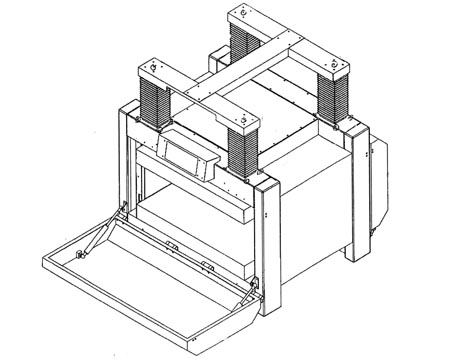
The method more commonly implemented today is the heat flow meter method mainly due to the fact that measurements are carried out in a promptly manner. It offers 3 possible variants in terms of equipment: symmetrical with one sample, symmetrical with two samples and asymmetrical with one sample, as well as double equipment, with the possibility for all these variants of having both a vertical and a horizontal layout. This article is going to focus on a symmetrical heat flow meter with one sample and horizontal layout. The following figure shows a diagram of this type of equipment:

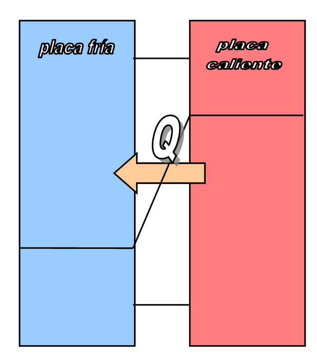
The equipment has two plates, a mobile one and a fixed one that while the test is being conducted shall be in perfect contact with the main sides of the material to be tested. To this end, the thickness of the test tube can be introduced (soft products) or the mobile plate can be moved until it puts specific pressure on the material (rigid products). In the central area of each plate, the measurement area, there is an embedded heat flow meter, which has thousands of small thermocouples. The average signal of each heat flow meter is proportional to the heat flow through the test tube and this signal is the one used to determine the thermal conductivity of the sample.
This test itself is a very simple physical experiment and entails the application of a temperature gradient, programming the plates at different temperatures so that a heat flow is produced through the sample. The temperature difference is calculated as the difference between the average temperatures in the centre of each plate.

In order to be able to accurately determine the thermal conductivity of the material, we shall be in a steady state, i.e., a series of balance criteria like the following shall be met:
- Temperature criterion: the plates shall have a stable temperature
- Criterion regarding the output signal of the heat flow meters: the signal of heat meters shall not vary
- Inflexibility criterion: The average signal of heat flow meters for the different groups of measurements taken by the equipment shall not vary in a monotonous way. The difference between the two successive groups shall change the sign or be equal to zero.
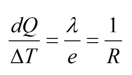
This way, it is possible to determine the thermal conductivity in the steady state of the material using the following equation:

where:
dQ is the heat flow, obtained from the calibration constants of the heat flow meters and from the electrical signal they provide (in W/m2)
ΔT is the temperature difference there is between the two sides of the sample (in K)
λ is the thermal conductivity of the sample (in W/m·K))
e is the thickness of the sample (in metres)
R is the thermal resistance of the sample (in m2·K/W)

